
 Search
 en
en English
 日本語
日本語 русский
 Español
 Deutsch
 中文简体
中文简体Content
- 1 What an Optical Reflector Actually Does
- 2 Reflector Types and Where Each One Belongs
- 3 Specifications to Fix Before You Request a Quote
- 4 Coatings Decide Reflectance, Durability, and Cost
- 5 Reflectors in Real Systems
- 6 Procurement Risks and Quality Checks
- 7 A Practical Selection Workflow
- 8 Frequently Asked Questions
A 100 W fiber laser cutter starts losing accuracy in a familiar way: the beam lands a few tenths of a degree off at the cutting head, and the operator spends the afternoon adjusting the nozzle instead of the optics. The part usually responsible is a 25 mm optical reflector that was chosen on price alone. A reflector looks like a flat piece of coated glass, but it sets beam position, energy throughput, and wavefront quality for every element downstream of it. The specifications below are the ones that decide whether a reflector holds its performance for five years or fails after five months.
What an Optical Reflector Actually Does
An optical reflector is a coated optical surface that redirects light along a controlled path with a defined reflectance, angle, and wavefront quality.
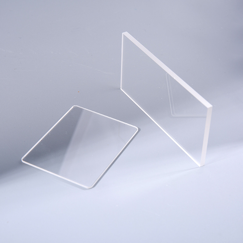
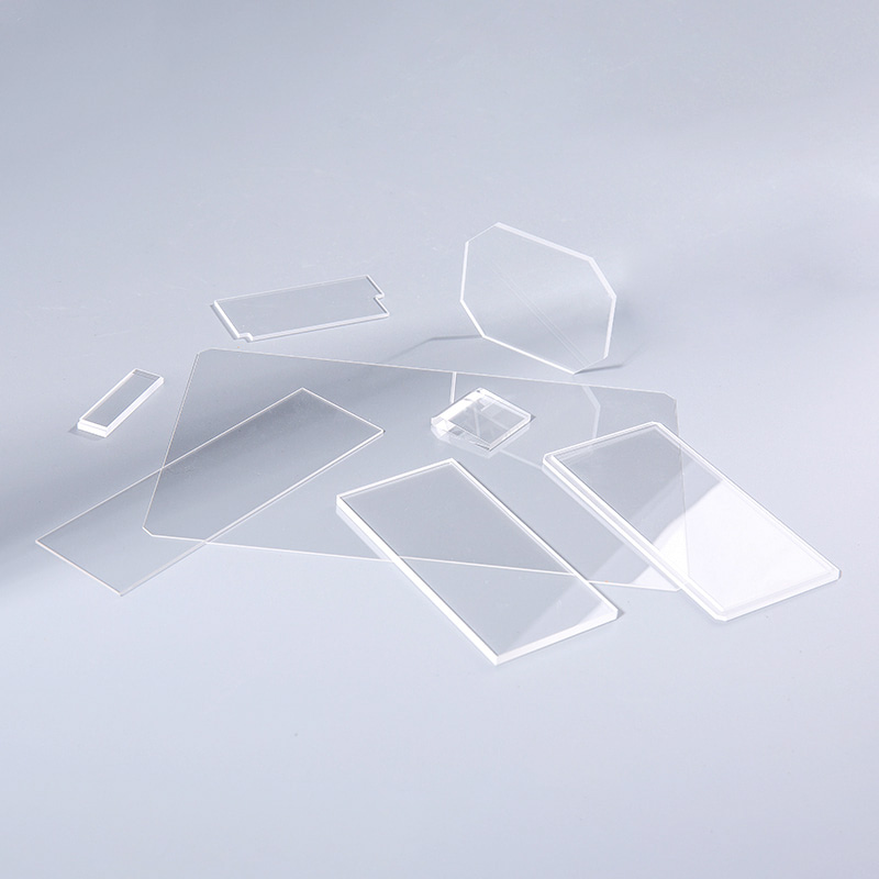
An optical reflector is a substrate, typically optical glass, fused silica, quartz, or sapphire, coated with either a protected metal film or a multilayer dielectric stack, so that light arriving at a stated angle of incidence leaves along a stated path with a rated reflectance across a stated wavelength band.
Two things separate an optical reflector from a decorative mirror: reflectance is specified across a wavelength band, and geometry is specified to an optical tolerance. A 45 degree plane reflector rated at 99.5 percent at 1064 nm is not interchangeable with a broadband aluminium mirror of the same diameter and thickness, even when both drop into the same mount.
Angle of incidence drives the coating design. Beam steering usually works at 45 degrees, cavity end mirrors at normal incidence, and some illumination layouts push to 60 degrees or beyond. Reflectance curves shift with angle, and at high angles a dielectric coating starts to split polarisation, which appears as an uneven beam profile after several folds in the same plane.
Surface flatness is the specification buyers underestimate most often. An irregularity in the polished surface shows up in the reflected wavefront at roughly twice its own value, because the light interacts with the surface twice in optical terms. A reflector specified at one wave flatness can therefore contribute about two waves of error to a system that budgeted only one.
Reflector Types and Where Each One Belongs
The geometries that cover most industrial work are the plane reflector, the concave spherical reflector, the convex spherical reflector, and the prism that reflects by total internal reflection.
| Reflector type | Geometry | Typical job | First spec to lock |
| Plane reflector | Flat surface, any substrate | Beam steering at 45 degrees, folding a laser path | Surface flatness and angle tolerance |
| Concave spherical reflector | Curved inward | Focusing, collimating, telescope primaries | Radius of curvature and focal length |
| Convex spherical reflector | Curved outward | Beam expansion, relay in imaging systems | Radius tolerance and centration |
| Prism reflector | Right-angle or roof prism | Compact 90 degree folding, image erecting | Angle accuracy and internal faces |
| Dielectric plane mirror | Flat, multilayer stack | High-power laser delivery, low loss paths | Damage threshold and reflectance band |
Flat reflectors dominate beam steering because the mount only has to control two angles. Curved reflectors do the same job plus focusing, so the radius of curvature must be held as tightly as the surface figure. A concave spherical reflector with a 200 mm radius used as a collimator loses focus quality quickly when the radius drifts by a few millimetres, even though the surface itself still looks perfect.
Specifications to Fix Before You Request a Quote
Six parameters decide whether two reflector quotations are genuinely comparable: substrate, flatness, surface quality, reflectance band, angle of incidence range, and coating durability.
| Parameter | Typical range | Why it matters |
| Substrate | BK7, fused silica, quartz, sapphire | Sets thermal stability and the transmission range the coating can work with |
| Surface flatness | 1 wave down to 1/10 wave over the clear aperture | Reflected wavefront error is roughly double the surface error |
| Surface quality | 60-40 to 10-5 scratch-dig | Scratches scatter light and can seed laser-induced damage |
| Reflectance band | 400-700 nm, 1064 nm, 3-5 um, 8-12 um | A coating rated for visible light will fail in the infrared |
| Angle of incidence | 0 to 45 degrees typical, up to 60 degrees | Reflectance curves shift with angle and polarisation |
| Coating durability | Adhesion, humidity, and abrasion tests | Determines cleaning cycles and service life in dirty environments |
Before sending an enquiry, confirm that the drawing you supply carries the following information. Suppliers who receive complete data quote faster and with fewer technical reservations.
- Clear aperture and the outer zone where coating and flatness are not guaranteed
- Wavelength, average power, pulse energy, and beam diameter at the optic
- Angle of incidence range, not just the nominal angle
- Environmental conditions: humidity, temperature swing, cleaning method, vibration
- Quantity per year, because coating runs are often batched
- Inspection requirements: reflectance measurement, interferometry report, or visual only
A reflector drawing without a clear aperture note is incomplete. Flatness and coating are normally specified only inside the clear aperture, and the outer 1 to 2 mm of a small optic can sit well outside that tolerance without anyone noticing until the beam clips the edge.
Coatings Decide Reflectance, Durability, and Cost
Protected metal coatings provide broadband reflectance at low cost, while dielectric multilayer stacks reach the highest reflectance in a narrow band and tolerate higher power density.
Protected metal coatings
- Broadband response from the visible into the infrared
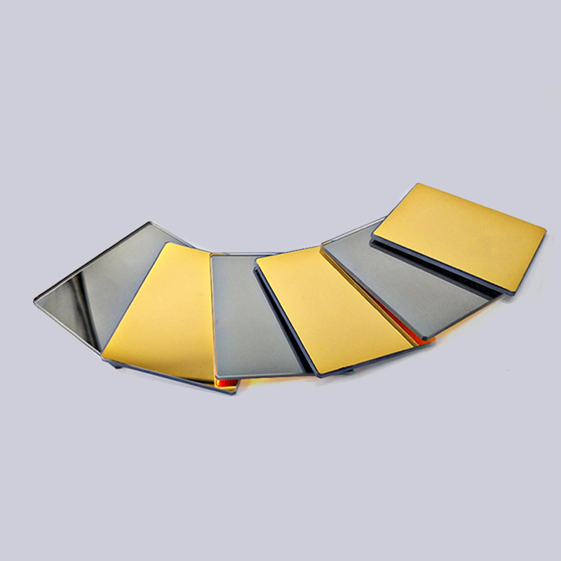
- Aluminium reaches 85 to 92 percent, silver 96 to 99 percent
- Lower unit cost and shorter deposition cycle
- Softer film, needs an overcoat, sensitive to aggressive cleaning
Dielectric multilayer coatings
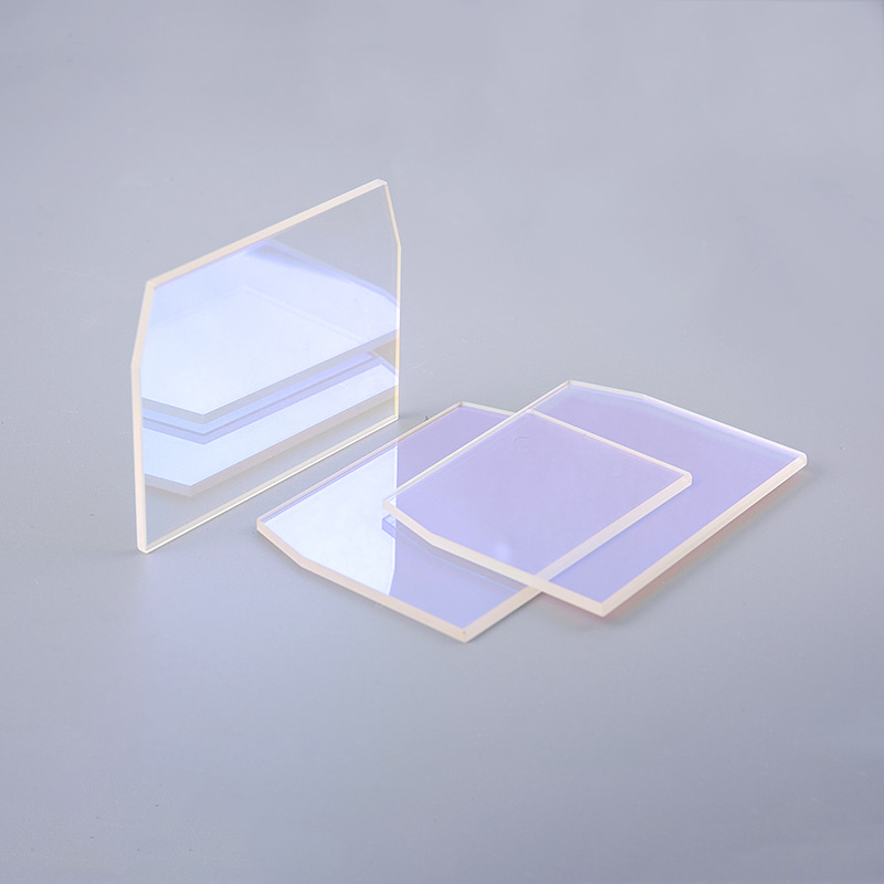
- Highest reflectance, up to 99.9 percent, inside a defined band
- Bandwidth narrows as target reflectance rises
- Hard, cleanable surface with a higher laser damage threshold
- Higher cost and longer lead time per coating run
Coating choice is also a cost decision. Moving from a protected aluminium reflector to a hard dielectric stack can multiply the unit price several times, but it may also double the service interval in a dirty industrial cell. The trade-off usually pays back when a single cleaning cycle forces a production stop. For a closer look at how layer design changes performance, see this explanation of how coatings on optical reflectors enhance their performance.
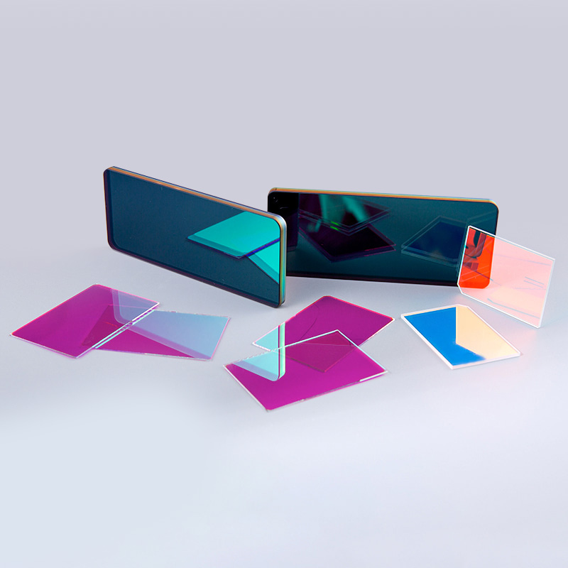
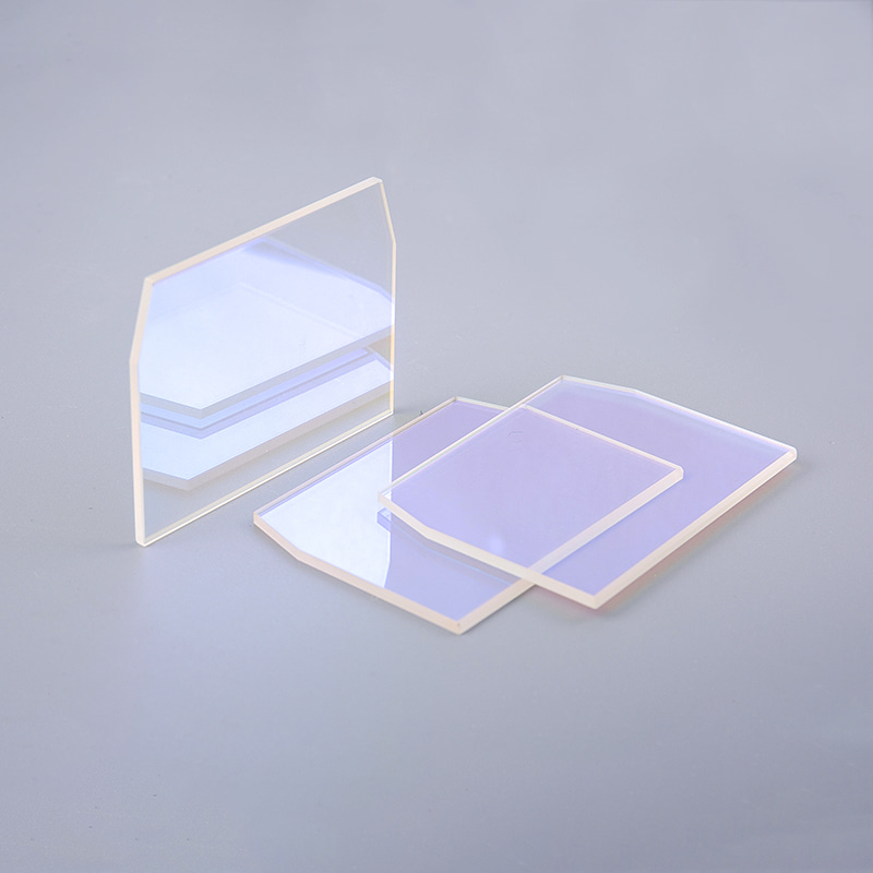 Custom Optical Reflector for Controlled Light ReflectionCustom optical reflector with key parameters such as reflectance, surface roughness, shape, and size for directing light in laser, medical, and research systems.View Product →
Reflectors in Real Systems
Reflectors appear in any system that must move, fold, or concentrate light, which in practice means laser processing, automotive sensing, illumination, instruments, semiconductor tools, and surveillance hardware.
Laser processing
Beam delivery on cutting, welding, and engraving machines relies on flat reflectors that survive continuous thermal load.
Automotive sensing
LiDAR units and head-up displays steer and fold pulsed light with compact coated mirrors.
Illumination
LED modules use shaped reflectors to collect wide-angle emission and push it into a usable beam.
Instruments
Telescopes, microscopes, and spectrometers use concave and flat reflectors where colour-free imaging matters.
Semiconductor tools
Inspection and metrology stages use reflectors and flat optics with sub-wave flatness over the aperture.
Surveillance
Housing windows and folding mirrors keep long lens assemblies compact in outdoor enclosures.
One pattern repeats across these applications: the reflector is rarely the most expensive component, but it is often the one that sets the alignment budget. A concave spherical reflector used in a LiDAR receiver, for example, has to hold both its radius and its centration, because any tilt of the curved surface converts directly into a pointing error at the detector.
 Custom Optical Spherical Mirrors, Concave and ConvexCustom concave and convex spherical mirrors for compact optical systems, laser beam shaping, microscopy, and applications where alignment and field of view matter.View Product →
Procurement Risks and Quality Checks
Most reflector failures in the field trace back to three causes: coating damage during cleaning, angular error from mounting or specification mistakes, and scatter from surface defects.
- Coating delamination after repeated solvent wiping, usually a sign of an unsealed metal film
- Reflectance drift when a coating specified for 45 degrees is installed at normal incidence
- Mount-induced stress that bends a thin substrate and adds wavefront error
- Edge chips that pass incoming inspection but spread contamination through a vacuum chamber
- Batch variation in radius or flatness that is invisible until the first article is measured
A supplier running an established quality system should be able to show a certificate, a measurement report for each batch, and a traceable coating run number. For automotive programmes, the relevant standard is IATF 16949 rather than ISO 9001 alone, and that distinction is worth checking before a reflector is designed into a production vehicle platform.
In sealed laser heads and outdoor enclosures, the reflector is normally protected by a separate optical window so that cleaning never touches the coated surface. Specifying the window and the reflector together, with matched flatness and transmission targets, removes a common source of rework during system integration.
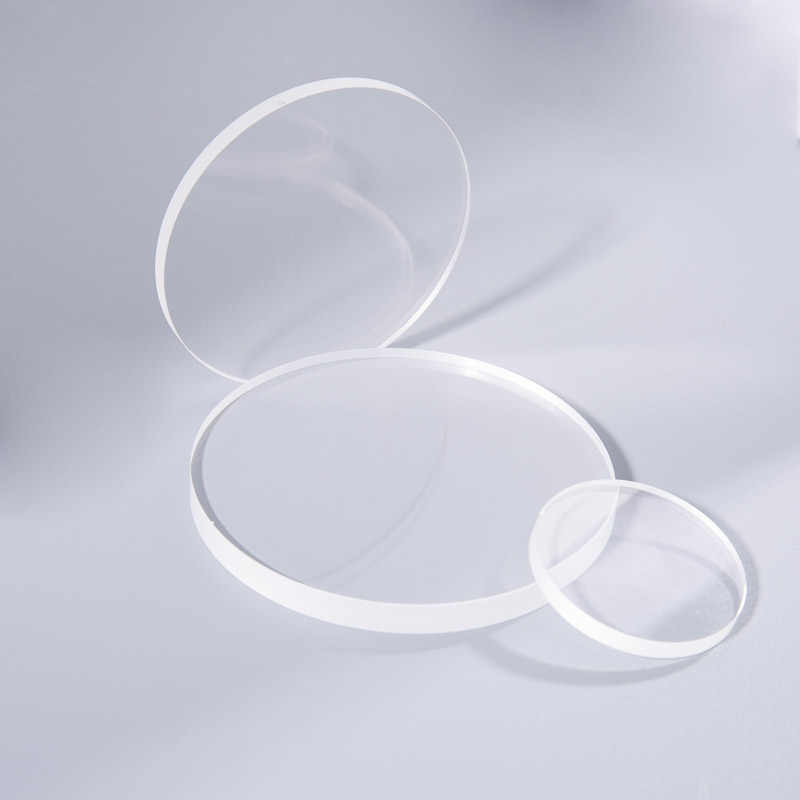 Custom Glass and Sapphire Optical WindowsGlass or sapphire optical windows that protect optical components and coated reflectors while allowing controlled transmission for lasers, photodiodes, and fiber systems.View Product →
A Practical Selection Workflow
A reflector specification becomes reliable when the optical function is defined before the dimensions, because the function decides which tolerances actually control performance.
- Define the optical function: steering, folding, focusing, or concentrating. This decides whether the surface is flat or curved.
- Fix the wavelength, average power, and angle of incidence range. Coating selection follows from these three numbers.
- Set the geometry tolerances: flatness or radius, clear aperture, thickness, and parallelism.
- Choose the coating family and the durability class, then confirm cleaning and handling rules with the supplier.
- Qualify the first article with a reflectance measurement, an interferometry report, and an adhesion check before releasing the batch.
Frequently Asked Questions
What is the difference between an optical reflector and a mirror?
A mirror is a general term for any reflective surface. An optical reflector is specified with a reflectance band, an angle of incidence, a surface figure tolerance, and a surface quality grade, which makes it measurable and repeatable in a system design.
Can one reflector work at any angle of incidence?
No. Coatings are deposited for a nominal angle, and reflectance curves shift as the angle changes and polarisation effects appear. A part designed for 45 degrees should not be used at normal incidence without re checking the reflectance and phase behaviour.
How long does a dielectric reflector coating last?
A hard dielectric stack usually outlasts a protected metal film by several times in the same environment, provided cleaning follows the supplier procedure. Service life then depends on humidity, temperature cycling, and how often the surface is touched.
What information does a supplier need to quote an optical reflector?
A drawing with clear aperture, flatness or radius, wavelength and power, angle of incidence range, quantity, and inspection requirements. Missing any of these usually produces a quotation with technical exclusions attached.
Reflector selection rewards a short, disciplined conversation at the start of a project. Nail down the function, the wavelength, and the angle first, then let geometry and coating follow, and the quotation you receive will be comparable to the next one. If a beam path has been giving trouble, it is worth having an engineer review the drawing before the next order, so please feel free to contact the engineering team with the wavelength, power, and mounting geometry you are working with.



 苏公网安备32041102000130号