
 Search
 en
en English
 日本語
日本語 русский
 Español
 Deutsch
 中文简体
中文简体Content
- 1 Direct Conclusion: The Essential Role and Inherent Limits
- 2 Surface Geometry and the Origin of Spherical Aberration
- 3 Key Specifications That Define Performance
- 4 Surface Figure Tolerances and Their Impact
- 5 Reflective Coatings and Spectral Performance
- 6 Practical Applications: From Telescopes to Laser Cavities
- 7 Mounting and Alignment Considerations
Direct Conclusion: The Essential Role and Inherent Limits
An optical spherical mirror is the most fundamental reflective element, featuring a surface that forms a section of a sphere. Its core advantage lies in cost-effective fabrication and straightforward interferometric testing, making it the default choice for applications ranging from astronomical telescopes to laser beam delivery. The immediate trade-off is spherical aberration: off-axis or non-paraxial rays do not converge to a single point, causing image blur unless the mirror operates at a high focal ratio or is combined with corrective optics. For systems that can tolerate this inherent aberration or use a slow beam, a spherical mirror delivers reliable, diffraction-limited performance without the complexity of aspheric surfaces.
Surface Geometry and the Origin of Spherical Aberration
A spherical mirror is defined by a single parameter: the radius of curvature. Parallel rays striking a concave spherical surface near the optical axis focus approximately at half that radius, the paraxial focal point. However, rays arriving farther from the axis intersect the axis at progressively shorter distances. The longitudinal spherical aberration grows rapidly with aperture. For a mirror of focal length f and diameter D, the angular blur diameter due to spherical aberration scales with (D/f)^3. At f/10 the aberration is often negligible for visual observation, while at f/4 a pure spherical mirror creates unusable image quality unless a Schmidt corrector plate or field lens is employed.
Convex spherical mirrors exhibit the opposite behavior, diverging light and creating a virtual focus. They are free from spherical aberration in the sense that they do not form a real image, but when used as secondary mirrors in Cassegrain-type telescopes their spherical shape still introduces system-level wavefront errors. The sign and magnitude of the conic constant are what distinguish a sphere (k=0) from a paraboloid (k=-1). Understanding this geometry explains why a simple spherical primary is reserved for systems where its low cost outweighs the need for high relative aperture.
Key Specifications That Define Performance
When selecting or specifying a spherical mirror, five parameters demand attention. They are tightly linked to the intended wavelength, beam size, and environment.
- Clear Aperture and Diameter Tolerance: Typically held to +0.0/-0.1 mm for optics under 50 mm. Larger telescope mirrors may have a diameter tolerance of ±0.5 mm.
- Radius of Curvature: The nominal value dictates focal length (f = R/2 for a concave mirror). Tolerances of ±0.5% are common, but laser cavity mirrors often require ±0.1% to maintain stable resonator modes.
- Surface Accuracy: Expressed in waves or fringes at 632.8 nm. Standard commercial quality is λ/4 peak-to-valley (PV), while precision laser and imaging systems demand λ/10 or better. A λ/20 mirror reduces the Strehl ratio loss to below 0.05.
- Surface Roughness: Typically 20 Å RMS or less for high-end protected silver coatings, critical to minimize scatter in ultraviolet and visible applications.
- Wedge and Centration: Edge thickness variation should stay under 0.1 mm to avoid beam deviation; centration is specified by the deviation of the optical axis from the mechanical axis, often kept within 3 arcminutes.
Surface Figure Tolerances and Their Impact
The surface figure of a spherical mirror directly governs the point spread function. A λ/4 PV spherical surface satisfies the Rayleigh criterion, delivering a Strehl ratio of approximately 0.80. For imaging systems where contrast is paramount, such as planetary observation or photolithography, λ/10 PV is the practical minimum. Interferometric testing with a reference sphere reveals low-order aberrations like astigmatism or trefoil, which can be introduced by improper mounting. The table below summarizes typical figure grades and their corresponding applications.
| Surface Accuracy (PV) | Typical Application | Strehl Ratio (approx.) |
|---|---|---|
| λ/2 | Illumination, non-critical relay | 0.40 |
| λ/4 | General lab, amateur telescopes | 0.80 |
| λ/10 | Laser cavities, high-resolution imaging | 0.95 |
| λ/20 | Interferometry, space optics | 0.99 |
It is important to note that figure error tolerances become tighter at shorter wavelengths. A λ/10 mirror at 633 nm becomes effectively λ/5 at 300 nm, drastically affecting ultraviolet performance. Therefore, specify surface accuracy at the actual operating wavelength whenever possible.
Reflective Coatings and Spectral Performance
A bare polished glass spherical mirror reflects only about 4% of incident light. Practical use demands a high-reflectivity coating, and the choice between metal and dielectric layers determines efficiency, bandwidth, and damage threshold.
Metal Coatings
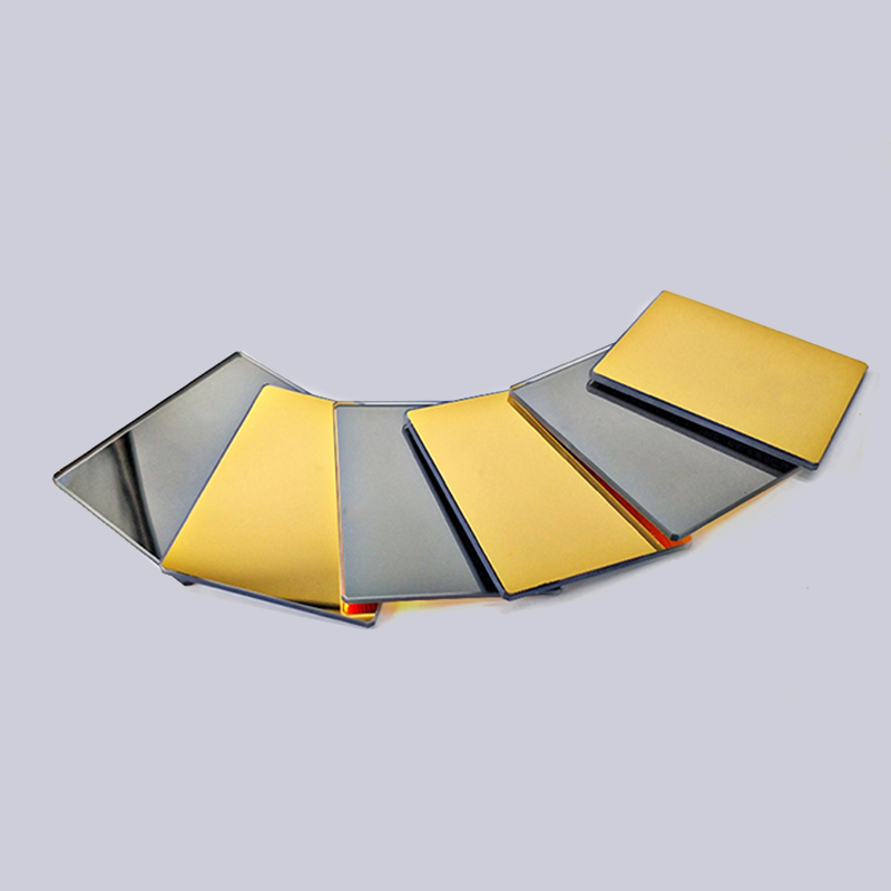
- Protected Aluminum: Broadband reflectivity of 87-93% across 400-700 nm, with a thin SiO2 overcoat. Averages R>90% from visible to near-infrared. Cost-effective for general optics.
- Protected Silver: Offers reflectivity above 95% from 500 nm to far-IR, but requires careful encapsulation to prevent tarnish. Popular in telescope secondary mirrors.
- Gold: Dominates the infrared beyond 2 μm, with reflectivity exceeding 98% above 5 μm. Inherently inert and often uncoated.
Dielectric Multilayers
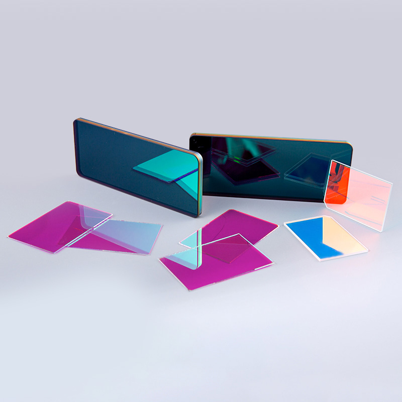
High-reflectance dielectric stacks achieve R > 99.9% over a narrow wavelength range. They are essential for laser gyroscopes, cavity end mirrors, and ultra-stable interferometers. The stack is designed for a specific angle of incidence; a coating specified for 0° will drop in performance when used at 45°.
Practical Applications: From Telescopes to Laser Cavities
Optical spherical mirrors appear wherever a simple, low-aberration focus is needed and the aperture is slow. In a Schmidt-Cassegrain telescope, the spherical primary is paired with a thin corrector plate that cancels spherical aberration, allowing a compact f/10 system with a full-field resolution of better than 1 arcsecond. In laser beam expanders, a concave spherical mirror collimates the diverging output of a single-mode fiber with minimal wavefront distortion. Many Fourier transform infrared spectrometers rely on gold-coated spherical mirrors to collect and redirect light without chromatic aberration.
Other notable examples include:
- Off-axis parabola simulators: A spherical mirror can serve as a calibration reference for interferometric testing of aspheric surfaces when its figure is known to λ/20.
- Ring-down spectroscopy cavities: High-finesse resonators formed by two concave spherical mirrors with dielectric coatings achieve reflectivities of 99.997%, enabling parts-per-trillion gas detection.
- Automotive LiDAR: Rotating polygonal spherical mirrors scan a 905 nm laser beam across the scene, leveraging the mirror's robustness and low cost.
Mounting and Alignment Considerations
Even an optical spherical mirror with a λ/20 surface figure can be degraded to λ/2 performance by poor mounting. Three-point kinematic mounts are standard, but the support locations and torque must be controlled. Finite element analysis shows that clamping a 100 mm diameter, 10 mm thick mirror at its edge can induce astigmatism exceeding 0.3 fringes if preload exceeds 0.5 Nm. Recommended practices include:
- Use nylon-tipped setscrews with a contact stress below 10 MPa to avoid micro-crazing.
- Orient the mirror so that the gravity vector aligns with the plane of the mount, minimizing sag.
- For cryogenic or vacuum operation, match the coefficient of thermal expansion between the mirror substrate and mount. Fused silica coupled with Invar or titanium is a proven combination.
- Temporary gluing during alignment should use RTV silicone applied in uniform 1 mm thick pads; rigid epoxy can distort the surface by more than 1 wave.
A well-mounted spherical mirror maintains its interferometrically verified figure, ensuring that the system operates at the specified Strehl ratio. The combination of correct surface specification, appropriate coating, and stress-free mounting is what turns a simple polished sphere into a precision optical tool.

 苏公网安备32041102000130号